ENGINE IMMOBILISER SYSTEM > TERMINALS OF ECU |
| CHECK TRANSPONDER KEY AMPLIFIER |

Disconnect the T20 amplifier connector.
Measure the resistance of the wire harness side connector.
| Symbols (Terminal No.) | Wiring Color | Terminal Description | Condition | Specified Condition |
| GND (T20-7) - Body ground | L-O - Body ground | Ground | Always | Below 1 Ω |
Reconnect the T20 amplifier connector.
Measure the resistance and voltage of the connector.
| Symbols (Terminal No.) | Wiring Color | Terminal Description | Condition | Specified Condition |
| GND (T20-7) - Body ground | L-O - Body ground | Ground | Always | Below 1 Ω |
| VC5 (T20-1) - GND (T20-7) | L - L-O | Power source | No key in ignition key cylinder | Below 1 V |
| Key inserted | 4.6 to 5.4 V | |||
| CODE (T20-4) - GND (T20-7) | L-Y - L-O | Demodulated signal of key code data | No key in ignition key cylinder | Below 1 V |
| Key inserted | Pulse generation (see waveform 1) | |||
| TXCT (T20-5) - GND (T20-7) | L-B - L-O | Key code output signal | No key in ignition key cylinder | Below 1 V |
| Key inserted | Pulse generation (see waveform 2) |
Inspect using an oscilloscope.
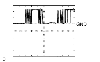 |
Waveform 1 (Reference)
| Symbols (Terminal No.) | Tool Setting | Condition |
| CODE (T20-4) - GND (T20-7) | 2 V/DIV., 20 msec./DIV. | Key inserted |
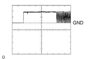 |
Waveform 2 (Reference)
| Symbols (Terminal No.) | Tool Setting | Condition |
| TXCT (T20-5) - GND (T20-7) | 2 V/DIV., 20 msec./DIV. | Key inserted |
| CHECK TRANSPONDER KEY ECU ASSEMBLY |

Disconnect the T21 ECU connector.
Measure the voltage and resistance of the wire harness side connector.
| Symbols (Terminal No.) | Wiring Color | Terminal Description | Condition | Specified Condition |
| AGND (T21-5) - Body ground | L-O - Body ground | Ground | Always | Below 1 Ω |
| GND (T21-16) - Body ground | G - Body ground | Ground | Always | Below 1 Ω |
| +B (T21-1) - GND (T21-16) | L-Y - G | Power source supply | Always | 10 to 14 V |
| IG (T21-2) - GND (T21-16) | B-O - G | Ignition power supply | Ignition switch OFF | Below 1 V |
| Ignition switch ON | 10 to 14 V | |||
| KSW (T21-3) - GND (T21-16) | BR - G | Unlock warning switch | No key in ignition key cylinder | 10 kΩ or higher |
| Key inserted | Below 1 Ω |
Reconnect the T21 ECU connector.
Measure the voltage of the connector.
| Symbols (Terminal No.) | Wiring Color | Terminal Description | Condition | Specified Condition |
| VC5 (T21-14) - AGND (T21-5) | L - L-O | Power source of transponder key amplifier | No key in ignition key cylinder | Below 1 V |
| Key is inserted | 4.6 to 5.4 V | |||
| CODE (T21-15) - AGND (T21-5) | L-Y - L-O | Transponder key amplifier communication signal | No key in ignition key cylinder | Below 1 V |
| Key is inserted | Pulse generation (see waveform 1) | |||
| TXCT (T21-4) - AGND (T21-5) | L-B - L-O | Transponder key amplifier communication signal | No key in ignition key cylinder | Below 1 V |
| Key is inserted | Pulse generation (see waveform 2) | |||
| EFIO (T21-13) - E0M (T21-11) | Y-G - W-B | ECM output signal | Ignition switch OFF | Below 1 V |
| Ignition switch ON | Pulse generation (see waveform 3) | |||
| EFII (T21-12) - E0M (T21-11) | Y-B - W-B | ECM input signal | Ignition switch OFF | Below 1 V |
| Ignition switch ON | Pulse generation (see waveform 4) |
Inspect using an oscilloscope.
|
Waveform 1 (Reference)
| Symbols (Terminal No.) | Tool Setting | Condition |
| CODE (T21-15) - AGND (T21-5) | 2 V/DIV., 20 msec./DIV. | Key inserted |
|
Waveform 2 (Reference)
| Symbols (Terminal No.) | Tool Setting | Condition |
| TXCT (T21-4) - AGND (T21-5) | 2 V/DIV., 20 msec./DIV. | Key inserted |
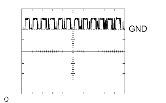 |
Waveform 3 (Reference)
| Symbols (Terminal No.) | Tool Setting | Condition |
| EFIO (T21-13) - E0M (T21-11) | 10 V/DIV., 100 msec./DIV. | Ignition switch ON |
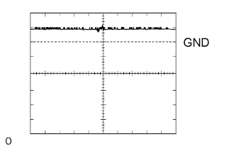 |
Waveform 4 (Reference)
| Symbols (Terminal No.) | Tool Setting | Condition |
| EFII (T21-12) - E0M (T21-11) | 10 V/DIV., 100 msec./DIV. | Ignition switch ON |
| CHECK ECM (2TR-FE) |
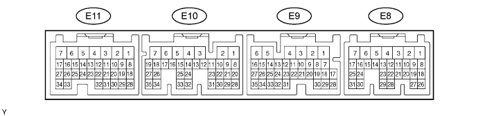
Measure the voltage and resistance of the connectors.
| Symbols (Terminal No.) | Wiring Color | Terminal Description | Condition | Specified Condition |
| IMI (E10-16) - E0M (E9-29) | Y-G - W-B | Transponder key ECU input signal | Ignition switch OFF | Below 1 V |
| Ignition switch ON | Pulse generation (see waveform 1) | |||
| IMO (E10-15) - E0M (E9-29) | Y-B -W-B | Transponder key ECU output signal | Ignition switch OFF | Below 1 V |
| Ignition switch ON | Pulse generation (see waveform 2) | |||
| E01 (E12-7) - Body ground | W-B - Body ground | Ground | Always | Below 1 Ω |
| E02 (E12-6) - Body ground | W-B - Body ground | Ground | Always | Below 1 Ω |
| EC (E9-22) - Body ground | R - Body ground | Ground | Always | Below 1 Ω |
Inspect using an oscilloscope.
|
Waveform 1 (Reference)
| Symbols (Terminal No.) | Tool Setting | Condition |
| IMI (E10-16) - E0M (E9-29) | 10 V/DIV., 100 msec./DIV. | Ignition switch ON |
|
Waveform 2 (Reference)
| Symbols (Terminal No.) | Tool Setting | Condition |
| IMO (E10-15) - E0M (E9-29)) | 10 V/DIV., 100 msec./DIV. | Ignition switch ON |
| CHECK ECM (1GR-FE) |
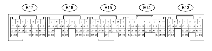
Measure the voltage and resistance of the connectors.
| Symbols (Terminal No.) | Wiring Color | Terminal Description | Condition | Specified Condition |
| IMI (E14-16) - E0M (E13-29) | Y-G - W-B | Transponder key ECU input signal | Ignition switch OFF | Below 1 V |
| Ignition switch ON | Pulse generation (see waveform 1) | |||
| IMO (E14-15) - E0M (E13-29) | Y-B -W-B | Transponder key ECU output signal | Ignition switch OFF | Below 1 V |
| Ignition switch ON | Pulse generation (see waveform 2) | |||
| E01 (E16-7) - Body ground | W-B - Body ground | Ground | Always | Below 1 Ω |
| E02 (E16-6) - Body ground | W-B - Body ground | Ground | Always | Below 1 Ω |
| EC (E13-22) - Body ground | R - Body ground | Ground | Always | Below 1 Ω |
Inspect using an oscilloscope.
|
Waveform 1 (Reference)
| Symbols (Terminal No.) | Tool Setting | Condition |
| IMI (E14-16) - E0M (E13-29) | 10 V/DIV., 100 msec./DIV. | Ignition switch ON |
|
Waveform 2 (Reference)
| Symbols (Terminal No.) | Tool Setting | Condition |
| IMO (E14-15) - E0M (E13-29)) | 10 V/DIV., 100 msec./DIV. | Ignition switch ON |
| CHECK ECM (1KD-FTV) |
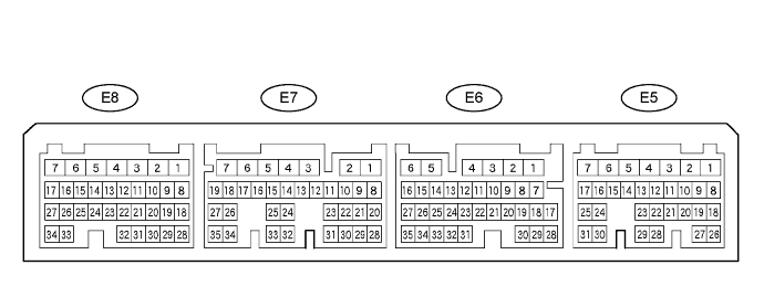
Measure the voltage and resistance of the connectors.
| Symbols (Terminal No.) | Wiring Color | Terminal Description | Condition | Specified Condition |
| IMI (E6-30) - E0M (E5-16) | Y-G - W-B | Transponder key ECU input signal | Ignition switch OFF | Below 1 V |
| Ignition switch ON | Pulse generation (see waveform 1) | |||
| IMO (E6-29) - E0M (E5-16) | Y-B -W-B | Transponder key ECU output signal | Ignition switch OFF | Below 1 V |
| Ignition switch ON | Pulse generation (see waveform 2) | |||
| E01 (E8-7) - Body ground | W-B - Body ground | Ground | Always | Below 1 Ω |
| E02 (E8-6) - Body ground | W - Body ground | Ground | Always | Below 1 Ω |
| E1 (E7-7) - Body ground | BR - Body ground | Ground | Always | Below 1 Ω |
Inspect using an oscilloscope.
|
Waveform 1 (Reference)
| Symbols (Terminal No.) | Tool Setting | Condition |
| IMI (E6-30) - E0M (E5-16) | 10 V/DIV., 100 msec./DIV. | Ignition switch ON |
|
Waveform 2 (Reference)
| Symbols (Terminal No.) | Tool Setting | Condition |
| IMI (E7-30) - E0M (E6-16) | 10 V/DIV., 100 msec./DIV. | Ignition switch ON |
