DTC P0627/78 Fuel Pump Control Circuit / Open |
| DTC No. | DTC Detection Condition | Trouble Area |
| P0627/78 | Open or short in suction control valve circuit for more than 0.5 seconds (1 trip detection logic) |
|
| Engine Speed | Fuel Pressure |
| Idling | Approximately 30 to 40 MPa |
| 3,000 rpm (No engine load) | Approximately 50 to 70 MPa |

| 1.INSPECT SUPPLY PUMP ASSEMBLY (SUCTION CONTROL VALVE) |
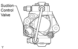 |
Disconnect the S8 suction control valve connector.
Measure the resistance of the suction control valve.
|
| ||||
| OK | |
| 2.CHECK WIRE HARNESS (SUCTION CONTROL VALVE - ECM) |
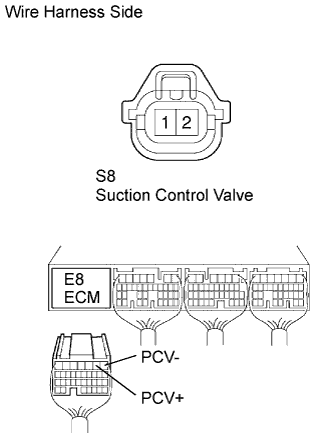 |
Disconnect the S8 valve connector.
Disconnect the E8 ECM connector.
Measure the resistance of the wire harness side connectors.
| Tester Connection | Specified Condition |
| S8-1 (PCV+) - E8-2 (PCV+) | Below 1 Ω |
| S8-2 (PCV-) - E8-1 (PCV-) | Below 1 Ω |
| S8-1 (PCV+) - E8-2 (PCV+) - Body ground | 10 kΩ or higher |
| S8-2 (PCV-) - E8-1 (PCV-) - Body ground | 10 kΩ or higher |
|
| ||||
| OK | |
| 3.CHECK ECM (PCV SIGNAL) |
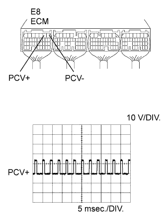 |
While cranking or idling the engine, check the waveform of the ECM connector using an oscilloscope.
| Tester Connection | Specified Condition |
| E8-2 (PCV+) - E8-1 (PCV-) | Correct waveform is shown |
| Tool Setting | Condition |
| 10 V/DIV., 5 msec./DIV. | Idling or cranking with warm engine |
|
| ||||
| OK | ||
| ||
