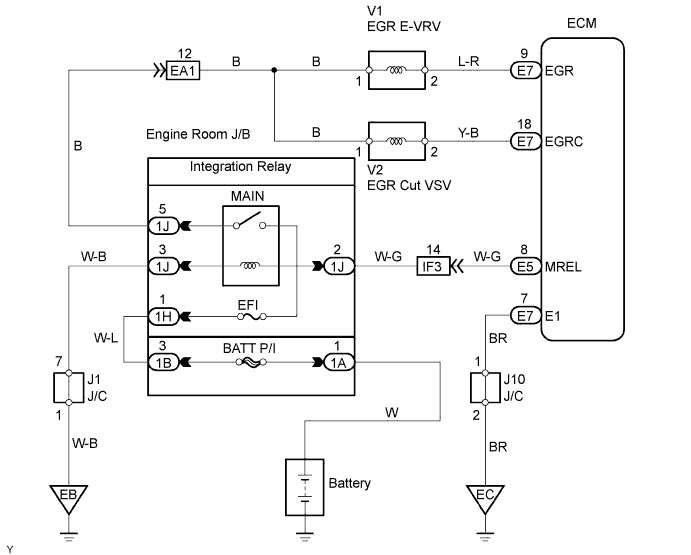
ECD SYSTEM > EGR Control Circuit |
| 1.CHECK CONNECTION OF VACUUM HOSE |
Check the connection of vacuum hose.
|
| ||||
| OK | |
| 2.CHECK VACUUM |
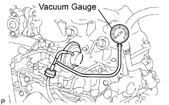 |
Using a 3-way connector, connect a vacuum gauge to the vacuum hose between the EGR E-VRV and EGR valve.
Warm up the engine to above 80°C (176°F).
Chck the vacuum at 1,500rpm.
| Vacuum | Proceed to |
| 0 kPa (0 mmHg, 0 in.Hg) | A |
| 0 kPa (0 mmHg, 0 in.Hg) to 28 kPa (210 mmHg, 8.3 in.Hg) | B |
| Above 28 kPa (210 mmHg, 8.3 in.Hg) | C |
|
| ||||
|
| ||||
| B | |
| 3.PERFORM ACTIVE TEST BY INTELLIGENT TESTER (EGR CUT VACUUM SWITCHING VALVE) |
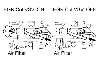 |
Disconnect the vacuum hose from the VSV.
Connect the intelligent tester to the DLC3.
Turn the ignition switch ON and turn the intelligent tester II ON.
Enter the following menus: Powertrain / Engine / Active Test / Activate the VSV for EGR Cut.
Check the operation.
|
| ||||
| NG | |
| 4.INSPECT EGR CUT VACUUM SWITCHING VALVE |
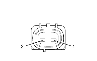 |
Disconnect the V2 VSV connector.
Measure the resistance of the VSV.
| Tester Connection | Condition | Specified Condition |
| 1 - 2 | 20°C (68°F) | 37 to 44 Ω |
|
| ||||
| OK | |
| 5.CHECK WIRE HARNESS (EGR CUT VACUUM SWITCHING VALVE - ECM) |
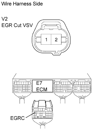 |
Disconnect the V2 VSV connector.
Disconnect the E7 ECM connector.
Measure the resistance of the wire harness side connectors.
| Tester Connection | Specified Condition |
| E7-18 (EGRC) - V2-2 | Below 1 Ω |
| E7-18 (EGRC) or V2-2 - Body ground | 10 kΩ or higher |
|
| ||||
| OK | |
| 6.CHECK WIRE HARNESS (EGR CUT VACUUM SWITCHING VALVE - MAIN RELAY) |
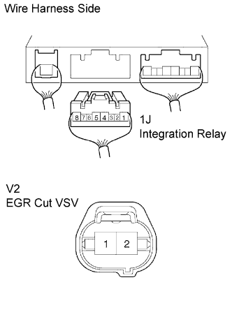 |
Remove the integration relay from the engine room J/B (Click here).
Disconnect the 1J integration relay connector.
Disconnect the V2 VSV connector.
Measure the resistance of the wire harness side connectors.
| Tester Connection | Specified Condition |
| 1J-5 - V2-1 | Below 1 Ω |
| 1J-5 or V2-1 - Body ground | 10 kΩ or higher |
|
| ||||
| OK | |
| 7.CHECK ECM (EGR VOLTAGE) |
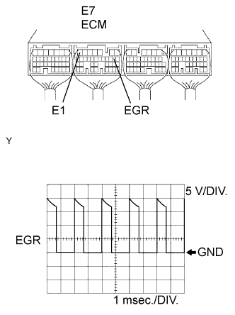 |
Disconnect the V1 E-VRV connector.
During idling, check the waveform of the ECM connector.
| Tester Connection | Specified Condition |
| E7-9 (EGR) - E7-7 (E1) | Correct waveform is as shown |
| Tool Setting | Condition |
| 5 V/DIV., 1 msec./DIV. | Idling with warm engine |
|
| ||||
| OK | |
| 8.CHECK OPERATION OF EGR ELECTRIC VACUUM REGULATING VALVE |
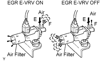 |
Disconnect the vacuum hoses from the E-VRV.
Connect the intelligent tester to the DLC3.
Turn the ignition switch ON and turn the intelligent tester ON.
Enter the following menus: Powertrain / Engine / Active Test / Control the EGR System.
Check the operation.
|
| ||||
| NG | |
| 9.INSPECT EGR ELECTRIC VACUUM REGULATING VALVE (RESISTANCE) |
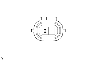 |
Disconnect the V1 E-VRV connector.
Measure the resistance of the E-VRV.
| Tester Connection | Condition | Specified Condition |
| 1 - 2 | 20°C (68°F) | 11 to 13 Ω |
|
| ||||
| OK | |
| 10.CHECK WIRE HARNESS (EGR ELECTRIC VACUUM REGULATING VALVE - ECM) |
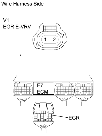 |
Disconnect the V1 E-VRV connector.
Disconnect the E7 ECM connector.
Measure the resistance of the wire harness side connectors.
| Tester Connection | Specified Condition |
| E7-9 (EGR) - V1-2 | Below 1 Ω |
| E7-9 (EGR) or V1-2 - Body ground | 10 kΩ or higher |
|
| ||||
| OK | |
| 11.CHECK WIRE HARNESS (EGR ELECTRIC VACUUM REGULATING VALVE - MAIN RELAY) |
 |
Remove the integration relay from the engine room J/B (see page ).
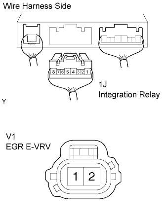
Disconnect the 1J integration relay connector.
Disconnect the V1 E-VRV connector.
Measure the resistance of the wire harness side connectors.
| Tester Connection | Specified Condition |
| 1J-5 - V1-1 | Below 1 Ω |
| 1J-5 or V1-1 - Body ground | 10 kΩ or higher |
|
| ||||
| OK | |
| 12.INSPECT EGR VALVE ASSEMBLY |
|
| ||||
| OK | ||
| ||
| 1.CHECK CONNECTION OF VACUUM HOSE |
Check the connection of vacuum hose.
|
| ||||
| OK | |
| 2.CHECK VACUUM |
|
Using a 3-way connector, connect a vacuum gauge to the vacuum hose between the EGR E-VRV and EGR valve.
Warm up the engine to above 80°C (176°F).
Chck the vacuum at 1,500rpm.
| Vacuum | Proceed to |
| 0 kPa (0 mmHg, 0 in.Hg) | A |
| 0 kPa (0 mmHg, 0 in.Hg) to 28 kPa (210 mmHg, 8.3 in.Hg) | B |
| Above 28 kPa (210 mmHg, 8.3 in.Hg) | C |
|
| ||||
|
| ||||
| B | |
| 3.INSPECT EGR CUT VACUUM SWITCHING VALVE |
|
Disconnect the V2 VSV connector.
Measure the resistance of the VSV.
| Tester Connection | Condition | Specified Condition |
| 1 - 2 | 20°C (68°F) | 37 to 44 Ω |
|
| ||||
| OK | |
| 4.INSPECT EGR CUT VACUUM SWITCHING VALVE (OPERATION) |
|
| ||||
| OK | |
| 5.CHECK WIRE HARNESS (EGR CUT VACUUM SWITCHING VALVE - ECM) |
|
Disconnect the V2 VSV connector.
Disconnect the E7 ECM connector.
Measure the resistance of the wire harness side connectors.
| Tester Connection | Specified Condition |
| E7-18 (EGRC) - V2-2 | Below 1 Ω |
| E7-18 (EGRC) or V2-2 - Body ground | 10 kΩ or higher |
|
| ||||
| OK | |
| 6.CHECK WIRE HARNESS (EGR CUT VACUUM SWITCHING VALVE - MAIN RELAY) |
|
Remove the integration relay from the engine room J/B (Click here).
Disconnect the 1J integration relay connector.
Disconnect the V2 VSV connector.
Measure the resistance of the wire harness side connectors.
| Tester Connection | Specified Condition |
| 1J-5 - V2-1 | Below 1 Ω |
| 1J-5 or V2-1 - Body ground | 10 kΩ or higher |
|
| ||||
| OK | |
| 7.CHECK ECM (EGR VOLTAGE) |
|
Disconnect the V1 E-VRV connector.
During idling, check the waveform of the ECM connector.
| Tester Connection | Specified Condition |
| E7-9 (EGR) - E7-7 (E1) | Correct waveform is as shown |
| Tool Setting | Condition |
| 5 V/DIV., 1 msec./DIV. | Idling with warm engine |
|
| ||||
| OK | |
| 8.INSPECT EGR ELECTRIC VACUUM REGULATING VALVE (RESISTANCE) |
|
Disconnect the V1 E-VRV connector.
Measure the resistance of the E-VRV.
| Tester Connection | Condition | Specified Condition |
| 1 - 2 | 20°C (68°F) | 11 to 13 Ω |
|
| ||||
| OK | |
| 9.INSPECT EGR ELECTRIC VACUUM REGULATING VALVE (OPERATION) |
|
| ||||
| OK | |
| 10.CHECK WIRE HARNESS (EGR ELECTRIC VACUUM REGULATING VALVE - ECM) |
|
Disconnect the V1 E-VRV connector.
Disconnect the E7 ECM connector.
Measure the resistance of the wire harness side connectors.
| Tester Connection | Specified Condition |
| E7-9 (EGR) - V1-2 | Below 1 Ω |
| E7-9 (EGR) or V1-2 - Body ground | 10 kΩ or higher |
|
| ||||
| OK | |
| 11.CHECK WIRE HARNESS (EGR ELECTRIC VACUUM REGULATING VALVE - MAIN RELAY) |
|
Remove the integration relay from the engine room J/B (Click here).
Disconnect the 1J integration relay connector.
Disconnect the V1 E-VRV connector.
Measure the resistance of the wire harness side connectors.
| Tester Connection | Specified Condition |
| 1J-5 - V1-1 | Below 1 Ω |
| 1J-5 or V1-1 - Body ground | 10 kΩ or higher |
|
| ||||
| OK | |
| 12.INSPECT EGR VALVE ASSEMBLY |
|
| ||||
| OK | ||
| ||
